


Photo by Jordan Harrison on Unsplash
MII signal bug in Xilinx FPGA
MII TX_EN signal goes low just for a clock cycle, which is a bug according to MII specifications.


The main goal of this article to give the general information about Ethernet packets and MII concept, and demonstrate a bug that I have recently faced while working on MII signals in Vivado, with the architecture that I build.
General information
The MII (Media-Independent Interface) was defined as a standard interface which connects MAC and PHY to each other. This interface is standardized by IEEE 802.3u protocol. In order to understand MII concept, first of all, we should comprehend Ethernet frame concept. In this blog post, packet and frame have the same meaning.
Ethernet frames
Ethernet frames can be transformed from MAC to PHY via MII signals. Standard Ethernet frames consist of Preamble, Start of Frame Delimiter, Ethernet Headers, Data, which is protocol-specific and finally CRC (Cyclic Redundancy Check) parts. There are two layer types for IEEE 802.3 protocol Ethernet packets and Layer 1 Ethernet packet which is important for the architecture that I built is shown below [1]:
 0                   1                   2                   3
 0 1 2 3 4 5 6 7 8 9 0 1 2 3 4 5 6 7 8 9 0 1 2 3 4 5 6 7 8 9 0 1
+-+-+-+-+-+-+-+-+-+-+-+-+-+-+-+-+-+-+-+-+-+-+-+-+-+-+-+-+-+-+-+-+
|                            Preamble                           |
+                                               +-+-+-+-+-+-+-+-+
|                                               |Frame Delimiter|
+-+-+-+-+-+-+-+-+-+-+-+-+-+-+-+-+-+-+-+-+-+-+-+-+-+-+-+-+-+-+-+-+
|                        MAC Destination                        |
+                               +-+-+-+-+-+-+-+-+-+-+-+-+-+-+-+-+
|                               |                               |
+-+-+-+-+-+-+-+-+-+-+-+-+-+-+-+-+                               +
|                           MAC Source                          |
+-+-+-+-+-+-+-+-+-+-+-+-+-+-+-+-+-+-+-+-+-+-+-+-+-+-+-+-+-+-+-+-+
|        Ethertype/Length       |                               |
+-+-+-+-+-+-+-+-+-+-+-+-+-+-+-+-+                               +
|                                                               |
+                       Payload(Variable)                       +
|                                                               |
+-+-+-+-+-+-+-+-+-+-+-+-+-+-+-+-+-+-+-+-+-+-+-+-+-+-+-+-+-+-+-+-+
|                              CRC                              |
+-+-+-+-+-+-+-+-+-+-+-+-+-+-+-+-+-+-+-+-+-+-+-+-+-+-+-+-+-+-+-+-+
|                                                               |
+                                                               +
|                        Interpacket Gap                        |
+                                                               +
|                                                               |
+-+-+-+-+-+-+-+-+-+-+-+-+-+-+-+-+-+-+-+-+-+-+-+-+-+-+-+-+-+-+-+-+
This figure is a general view of Ethernet packets. In an Ethernet frame, there should be some starting bytes which PHY side can comprehend that a new packet starts to be received. Therefore, for this purpose, Preamble and Start of Frame Delimiter parts are utilized. In these parts, specified bytes are sent to PHY (However, in some layers, which use Layer 2 Ethernet frame, these parts are ignored for gaining more bandwidth.). These bytes are 55 55 55 55 55 55 55 5D, which last byte indicates the Start of Frame Delimiter part and rest of them indicate Preamble part.
After these parts, MAC should transmit 6 byte MAC destination IP, which is for specifying the ending point, and also its 6 byte MAC source IP, which is for informing the end point about starting point. For example, for an ARP Ethernet frame, MAC destination IP is FF FF FF FF FF FF in order for MAC to know many PHY IP addresses (destination IP addresses) as much as possible.
Following these starting bytes, for IEEE 802.3 protocol, 2 bytes Ether type/Length part should be sent. If Ether type/Length value is less than 1500, the value shows the payload part size/length. Otherwise, it shows the Ether type/Length of the Ethernet packet. For example, if Ether type/Length part is 0x0800, it means that the packet is an IPv4 frame, if it is 0x0806, the packet is an ARP frame… etc.
Before FCS (Frame Check Sequence), or CRC (Same meaning but FCS name is specified for Ethernet frames.), Payload part which contains protocol’s headers (UDP checksum… etc.), main data, and padding bytes (if frame length is not long enough) should be transmitted.
At last, 4 bytes CRC/FCS information is sent by MAC. CRC is utilized for being sure that MAC addresses, Ether type/Length and Payload parts are correctly received by PHY side. For calculating it, some algorithms, which are not in our scope are used. For Ethernet packets, specifically, CRC32 BZIP2 is used [1]. Main calculations do not change among CRC types, but only parameters used for calculating CRC may differ.
Some specified parts, which can be seen in the figure above, are sent and finally, according to the Layer 1 Ethernet packets, Inter-Packet Gap phase starts. In this part, MAC transmits idle bytes to PHY so that PHY can receive previous packet and make some processes on the packet before new packet arrives. Briefly, MAC side should give some time to PHY side. In the figure, inter-packet gap is shown as 12 octets (bytes) but with respect to Ethernet speed, this number can change. Full Ethernet speed-inter packet gap duration list can be found below [3]:
| Ethernet Speed | Least Interpacket Gap Duration |
| 10 Mbits/s | 9.6 us |
| 100 Mbits/s | 0.96 us |
| 1 Gigabit/s | 96 ns |
| 2.5 Gigabit/s | 38.4 ns |
| 5 Gigabit/s | 19.2 ns |
| 10 Gigabit/s | 9.6 ns |
| 25 Gigabit/s | 3.84 ns |
| 40 Gigabit/s | 2.4 ns |
| 50 Gigabit/s | 1.92 ns |
| 100 Gigabit/s | 0.96 ns |
| 200 Gigabit/s | 0.48 ns |
| 400 Gigabit/s | 0.24 ns |
100 Mbits/s speed is used. Therefore, interpacket gap should be at least 0.96 us which means at least 96 bits (12 octets).The summary of Ethernet packet concept is referred above. So as to close to the main problem, we should comprehend MII concept as well.
MII signals
Standard MII signals transfer specified Ethernet frame using 4-bit (nibbles) with full-duplex way. However, by the time, different MII concepts were utilized in order to reduce signals and increase speed [^2f]. RMII (Reduced Media-Independent Interface), GMII (Gigabit Media-Independent Interface) and RGMII (Reduced Gigabit Media-Independent Interface) are different variants of MII so as to improve signals or speeds. However, I have utilized standard MII to achieve my goal. In the standard MII, there are some transmitter and receiver signals which are demonstrated below [2]:
| Signal Name | Description | Direction |
| TX_CLK | Transmit clock | MAC → PHY |
| TXD0 | Transmit data bit 0 which carries ethernet packet data | MAC → PHY |
| TXD1 | Transmit data bit 1 which carries ethernet packet data | MAC → PHY |
| TXD2 | Transmit data bit 2 which carries ethernet packet data | MAC → PHY |
| TXD3 | Transmit data bit 3 which carries ethernet packet data | MAC → PHY |
| TX_EN | Transmit enable signal which tells PHY that there are MII signals on their way | MAC → PHY |
| TX_ER | Transmit error signals which tells PHY there is a nibble error on its way | MAC → PHY |
| RX_CLK | Receive clock | PHY → MAC |
| RXD0 | Receiver data bit 0 which carries ethernet packet data | PHY → MAC |
| RXD1 | Receiver data bit 1 which carries ethernet packet data | PHY → MAC |
| RXD2 | Receiver data bit 2 which carries ethernet packet data | PHY → MAC |
| RXD3 | Receiver data bit 3 which carries ethernet packet data | PHY → MAC |
| RX_EN | Receiver enable signal which MAC knows MII signals are sent to it | PHY → MAC |
| RX_ER | Receiver error signals which MAC knows the MII signals have data errors | PHY → MAC |
| CRS | Carrier sense signal which is not used in the architecture | PHY → MAC |
| COL | Collision detect signal which is not used in the architecture | PHY → MAC |
Finally, after some general information, it is time to explain the architecture that is built.
Architecture
In fact, the architecture is very easy to construct and run. Below, the block design is shown:
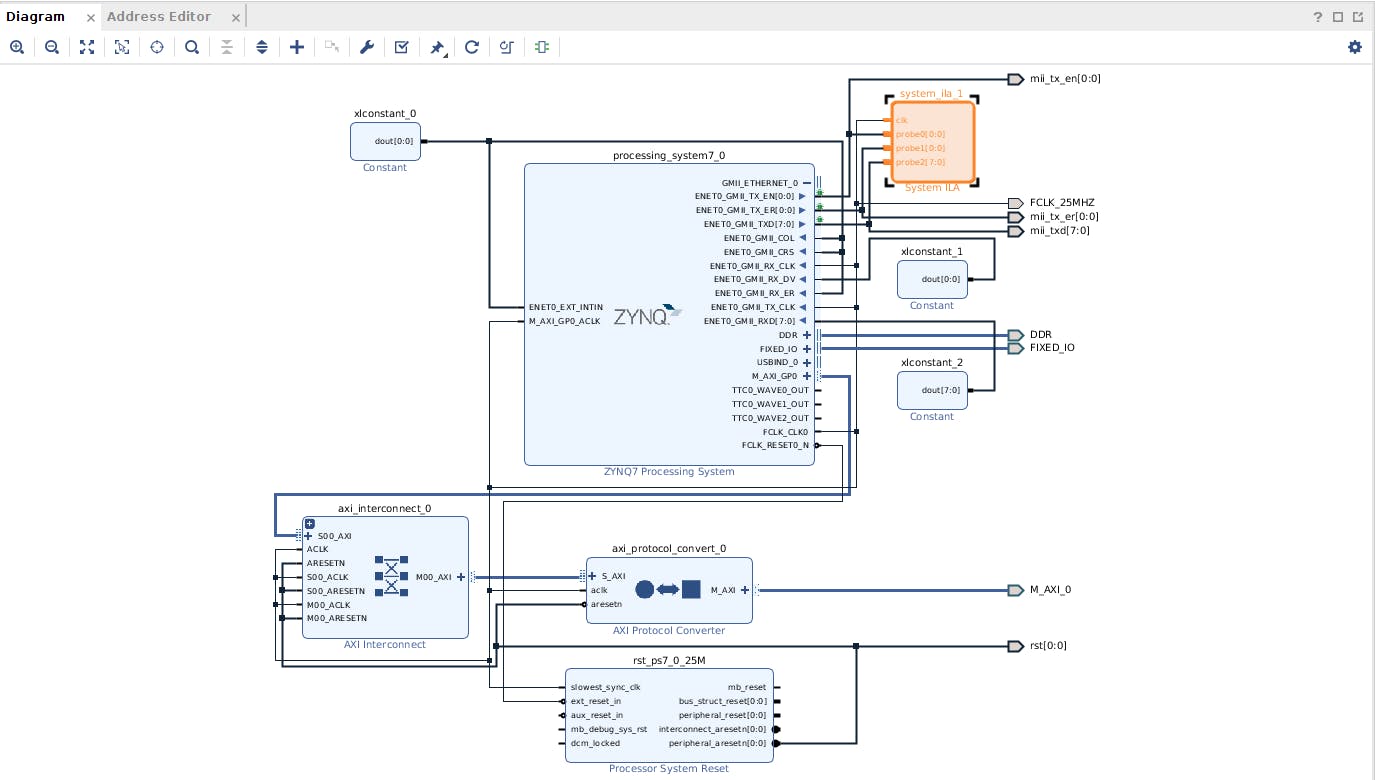
M_AXI_GP0, ENET0_GMIIRX and also some blocks such as AXI Interconnect, Processor System Reset, AXI Protocol Converter can be seen. These signals and blocks are nothing to do with ENET0_GMIITX. They do not affect TX side in any ways.As can be seen from the figure, there are just four signals that should be taken into consideration. These signals are ENET0_GMII_TX_EN, ENET0_GMII_TX_ER, ENET0_GMII_TXD, ENET0_GMII_TX_CLK. Because the speed is chosen as 100 Mbits/s, 25 MHz clock is generated via ZYNQ Block and connected to ENET0_GMII_TX_CLK. Other TX signals are connected to ILA Block to make some chipscope tests.
Moreover, I have utilized Linux Driver to set up transmission with ZYNQ GEM. In a more understandable language, I have used Linux Driver so that ARM side can generate Ethernet packets and send them via MII interface.
As a result, after building this, generating bitstream and programming device, I have started to observe MII signals and comprehend how they are sent via ILA. However, in some packets, I have found a bug that is explained in the next part.
The bug
According to MII Protocol Specification, during TX_EN signal assertion, receiver side takes the nibbles (for standard MII). When TX_EN signal goes low, receiver side takes the entire packet until that time and makes some process (such as calculating CRC and comparing with the received one) on the packet during interpacket gap time. Therefore, when TX_EN signal is not high after some transmission, receiver side understands that the packet is finished and it is time to make some processes.
However, in my architecture, sometimes, in the middle of packet, TX_EN signal goes low for a single clock cycle and then again goes high. So, it does not stay low for 24 clock cycles (12 octets) after it goes low. Also, so that I am sure that it is a bug, I have written a module that writes MII data to BRAM. For bug case, I have calculated CRC without including the case that TX_EN goes low and I have compared the calculated CRC with the received CRC. They were exactly the same.
This kind of bug can result in some errors in receiver side because people write codes according to the specifications and if you do not satisfy them, there always occur some errors and bugs. I have put some screenshoots from ILA to comprehend the problem more easily:
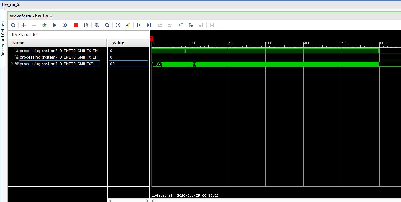
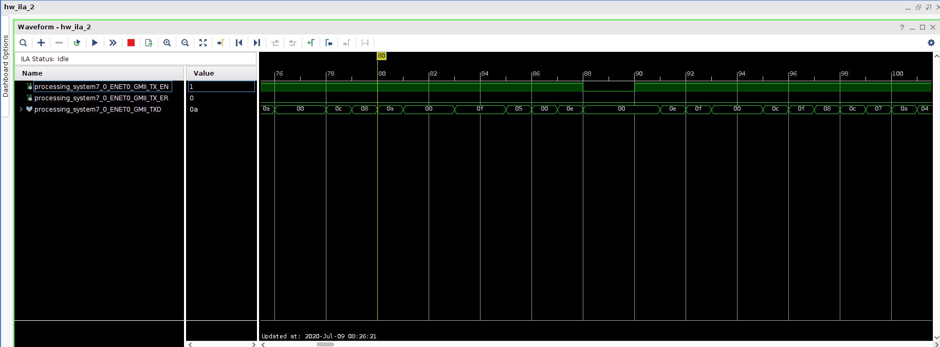
As can be inferred from the pictures, somewhere in the middle of the entire MII packet, TX_EN goes low. We can say that a packet transmission has finished and a new one has started but they are not two separate packets according to my CRC calculations. Because they unite a packet, TX_EN should not be deasserted even for a single clock cycle.
Finally, for this bug, I have posted a detailed question on Xilinx Forum but Xilinx employees do not really give attention to the bug. That is why there is no solution for this problem.